
 X1 / X4 product catalogueProduct catalogue / 2026
Product catalogue / 2026
Clarityunderpressure.
X1/X4
Diesel injector test systems
X1 / 01 CHANNELX4 / 04 CHANNELS
Engineered and manufactured byKOMTEST
English editionINJECTUNE.COM
X1 / X4 product catalogueProduct catalogue / 2026Product catalogue / 2026
Diesel injector test systems
Engineered and manufactured byKOMTEST
English editionThe product rangeProduct catalogue / 2026INJECTUNE / X1 + X4 + CONTROL
Two common rail injector benches. Choose one channel for individual diagnosis or four channels for injector-set comparison. Both platforms connect testing, supported coding and reporting in Injectune Control.
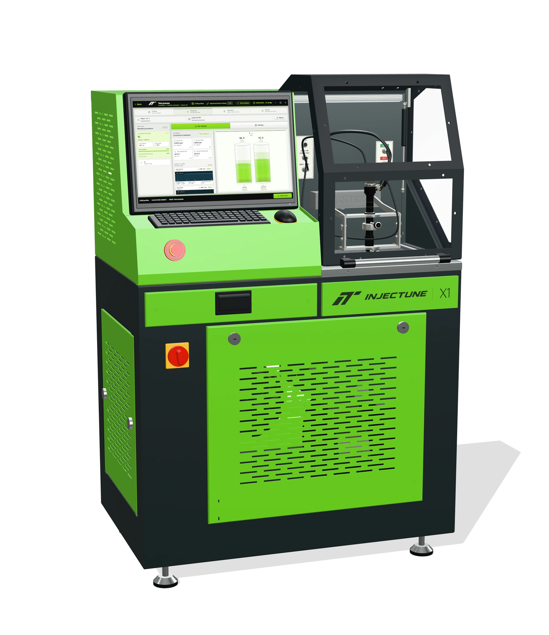 X1
Focused injector diagnosis and calibration
01 / Injector channel04 →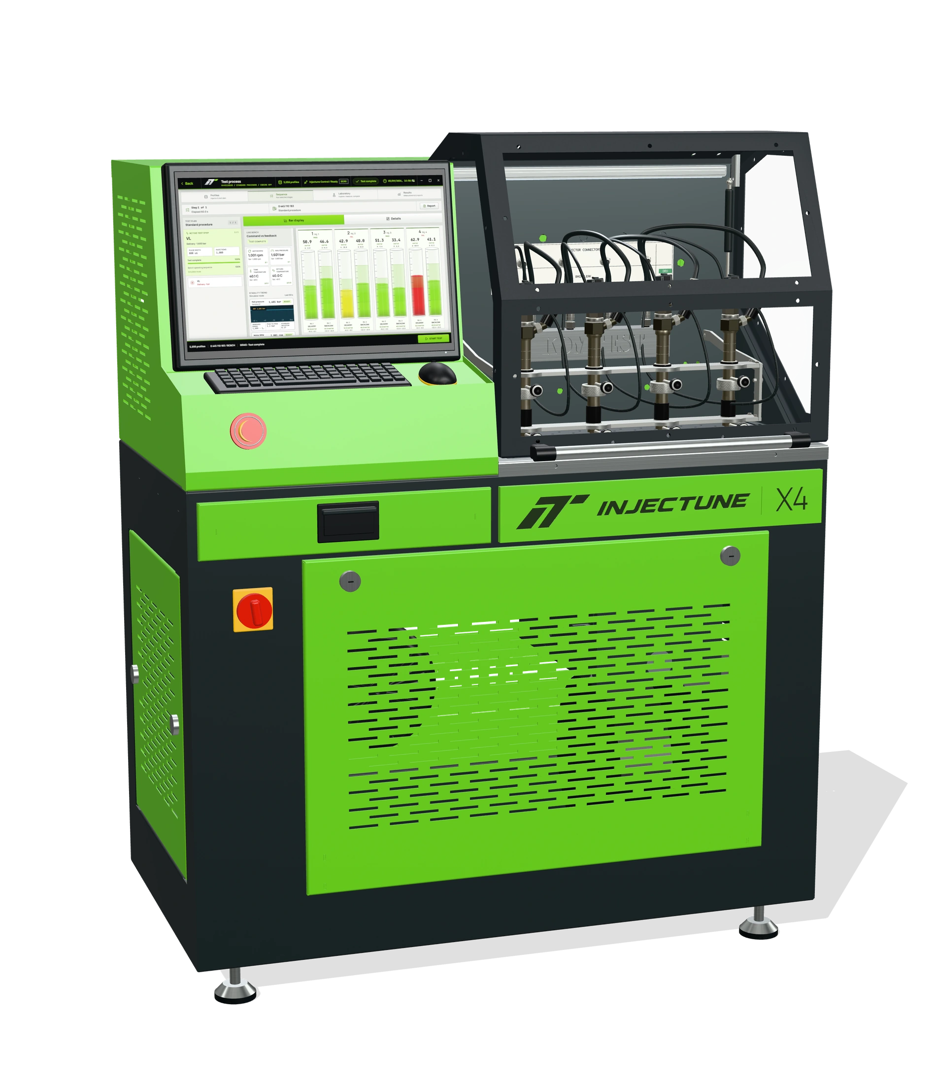 X4
Complete injector-set testing and comparison
04 / Injector channels06 →Product presentation. Final equipment and fixtures follow the agreed configuration.
X1 / X4 technical comparisonProduct catalogue / 2026X1 / X4
| Capability | Injectune X1 | Injectune X4 |
|---|---|---|
| Injector channels | 1 | 4 |
| Common rail pressure | 200–2,500 bar | 200–2,500 bar |
| Injector pulse control | Up to 3,000 μs | Up to 3,000 μs |
| Temperature tolerance | ±1 °C | ±1 °C |
| Automatic / manual testing | Included | Included |
| Graphical delivery / spill | Included | Included |
| Start Time | Included | Included |
| Electronic injector pairing | Supported | Supported |
| Injector coding | IMA · ISA · C2i · C3i · C4i · QR · IIC | IMA · ISA · C2i · C3i · C4i · QR · IIC |
| Report workflow | Save and print | Save and print |
| Drive | Speed-controlled AC motor | Speed-controlled AC motor |
| Control interface | PC, keyboard and mouse | PC, keyboard and mouse |
Coding, application coverage and fixtures depend on the installed configuration. Confirm machine dimensions, utilities and final equipment with the technical team before installation.
Injectune X1Product catalogue / 2026COMMON RAIL / X1
Injectune X1 brings common rail injector testing and coding into a focused single-channel workstation. Guided setup, graphical delivery and spill measurement, application-specific routines and printable reports keep the operator connected to every result.
Product presentation. Final equipment and fixtures follow the agreed configuration.
X1 / Workstation detailsProduct catalogue / 2026Injectune X1 / COMMON RAIL
Focused single-piece flow

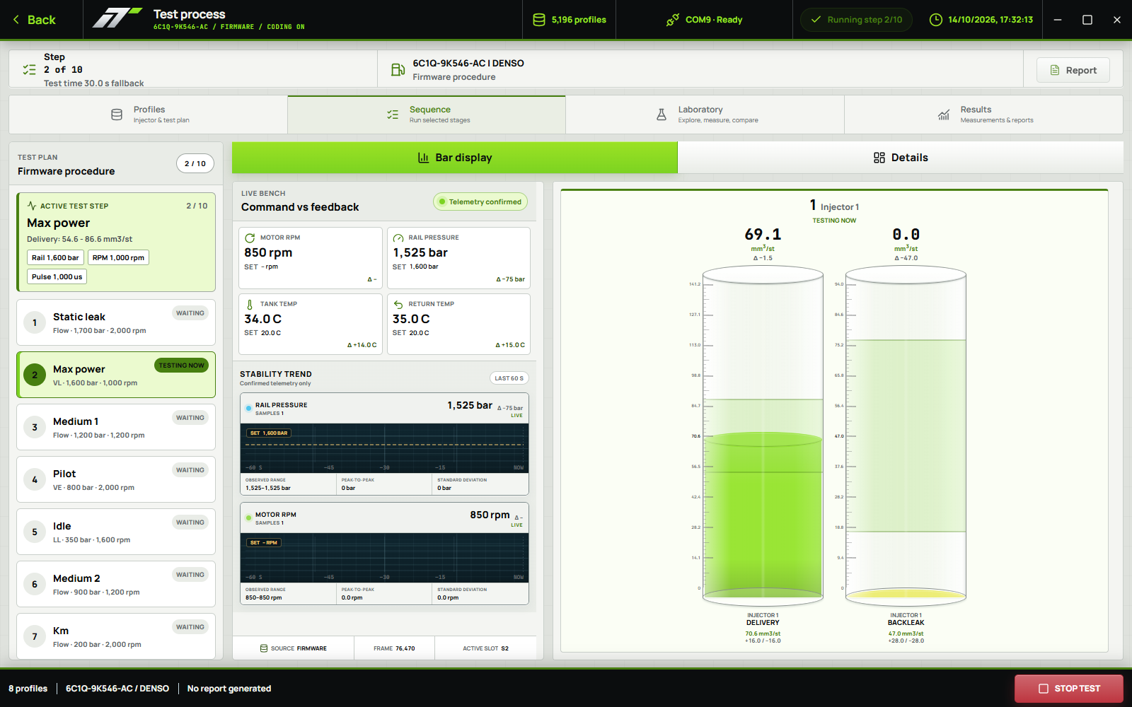
Select the injector profile, set the test conditions and follow the result from the PC, keyboard and mouse. Save or print the technical report from the same software environment.
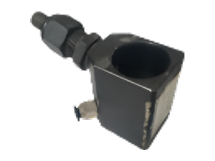
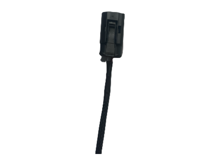
Application-specific fixtures position the injector in the working area. Select the sleeve, connection and electrical harness by the complete injector reference.
The injector uses separate pressure and return connections. The selected application determines the fittings, test conditions and measurement routine.
Final fixtures follow the agreed configuration. English application interface with recorded bench data for illustration. Profiles, functions and routines depend on the installed configuration.
Injectune X4Product catalogue / 2026COMMON RAIL / X4
Injectune X4 brings common rail injector testing, coding and matching into a coordinated four-channel workflow. Simultaneous channel visibility, electronic pairing, graphical measurement and printable reports help workshops compare injector sets and document each result.
Product presentation. Final equipment and fixtures follow the agreed configuration.
X4 / Workstation detailsProduct catalogue / 2026Injectune X4 / COMMON RAIL
Simultaneous channel visibility


Select the injector profile, set the test conditions and follow the result from the PC, keyboard and mouse. Save or print the technical report from the same software environment.
Application-specific fixtures position the injector in the working area. Select the sleeve, connection and electrical harness by the complete injector reference.
The injector uses separate pressure and return connections. The selected application determines the fittings, test conditions and measurement routine.
Final fixtures follow the agreed configuration. English application interface with recorded bench data for illustration. Profiles, functions and routines depend on the installed configuration.
Measurement & controlProduct catalogue / 2026INJECTUNE CONTROL / X1 + X4
A meaningful result links the injector, test conditions, measured quantity and applicable limits.
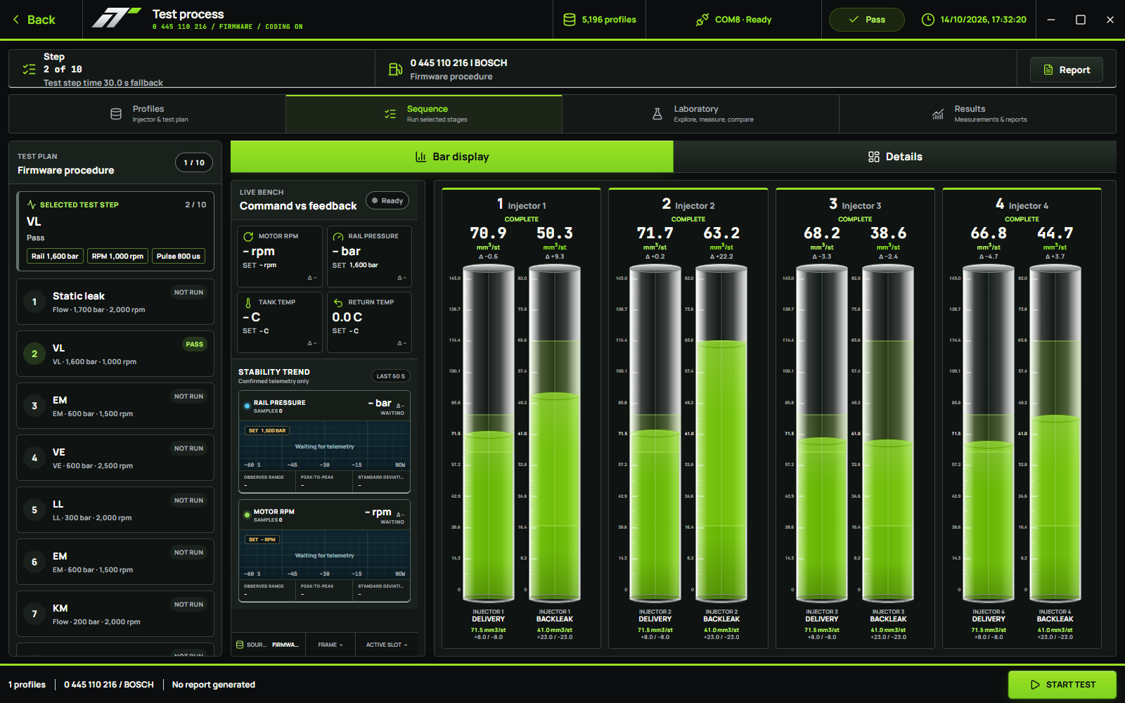
Fluid delivered through the nozzle during the test. Compare the displayed quantity and unit with the limits for that specific test point.
Fluid returned through the injector return circuit. Return flow is part of injector operation; interpret it against the plan rather than assuming every return is a fault.
Review the timing reported by the supported Start Time routine. Its definition and evaluation depend on the injector profile; it is distinct from commanded pulse width.
Compare compatible injectors under the same plan and conditions. Similar readings alone do not establish that every injector is within specification.
English application interface with recorded bench data for illustration. Profiles, functions and routines depend on the installed configuration.
Injectune Control / WorkflowProduct catalogue / 2026SOFTWARE / X1 + X4
Each step makes the next decision clearer.
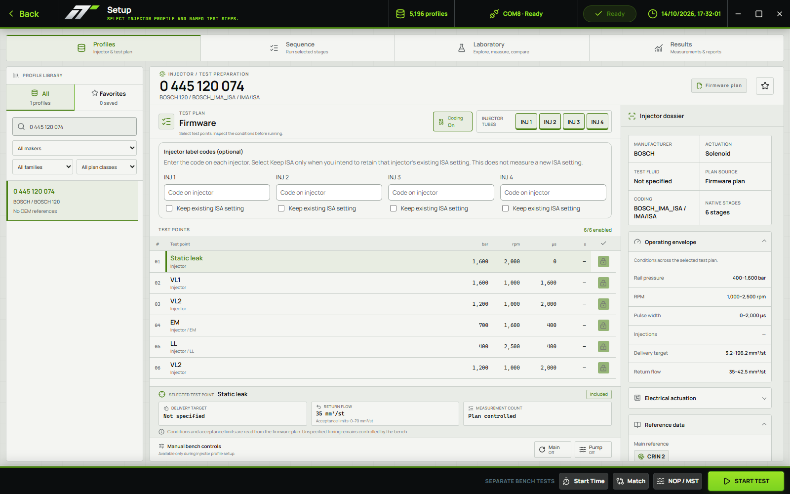
Find the injector by reference, manufacturer or family. Review the profile, connection and enabled test stages.
Follow the active test stage, command versus feedback and delivery values. Use automatic or manual operation as required.
Review the result by test stage, then save or print the technical protocol for the workshop and customer record.
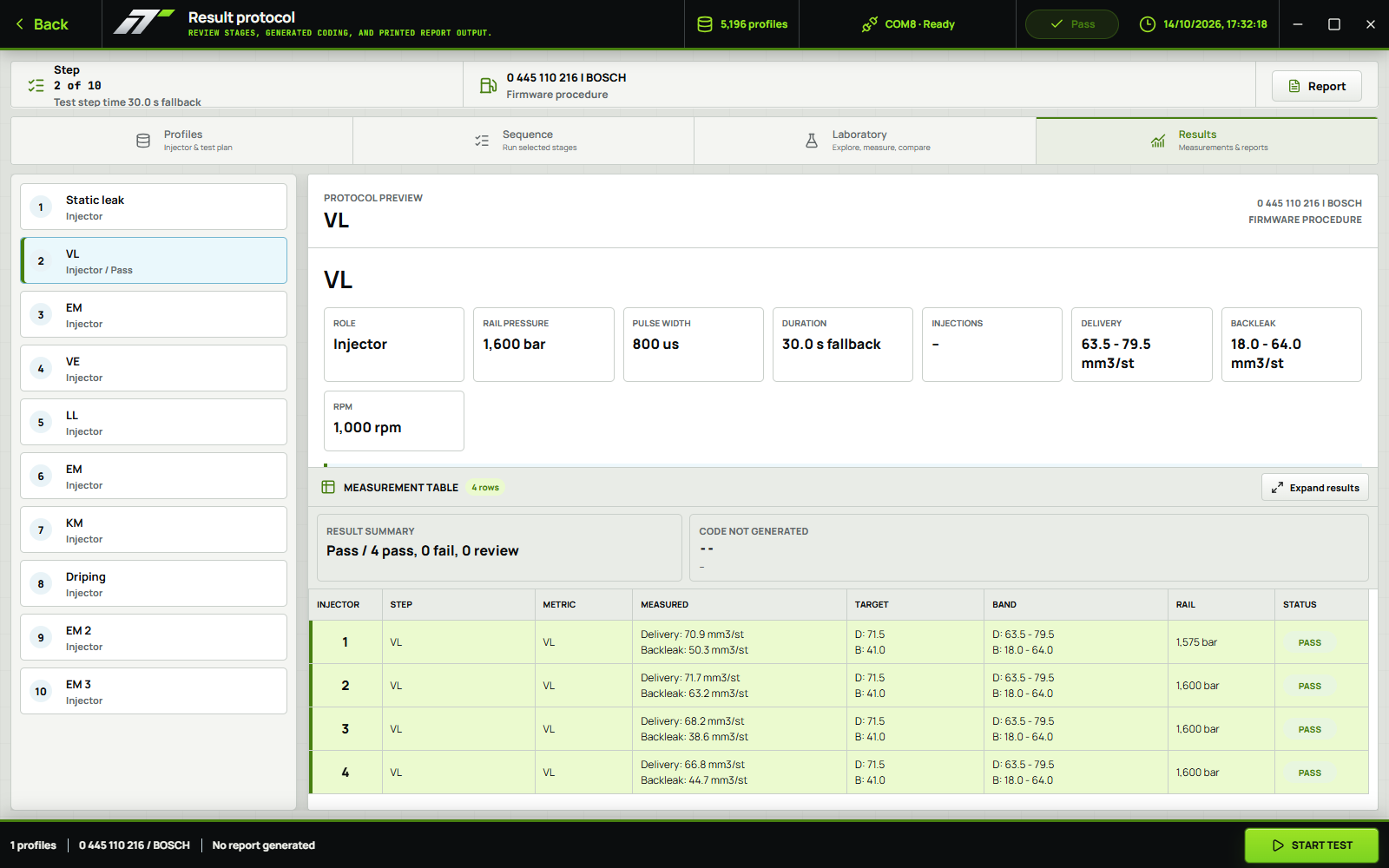
English interface examples. Test and report views show recorded data for illustration; they are not a new live test.
Coding & applicationsProduct catalogue / 2026IMA / C2i / C3i / C4i / QR / IIC
Supported coding routines stay connected to the injector profile and test result. Select the application first; confirm the required measurements before generating a code.
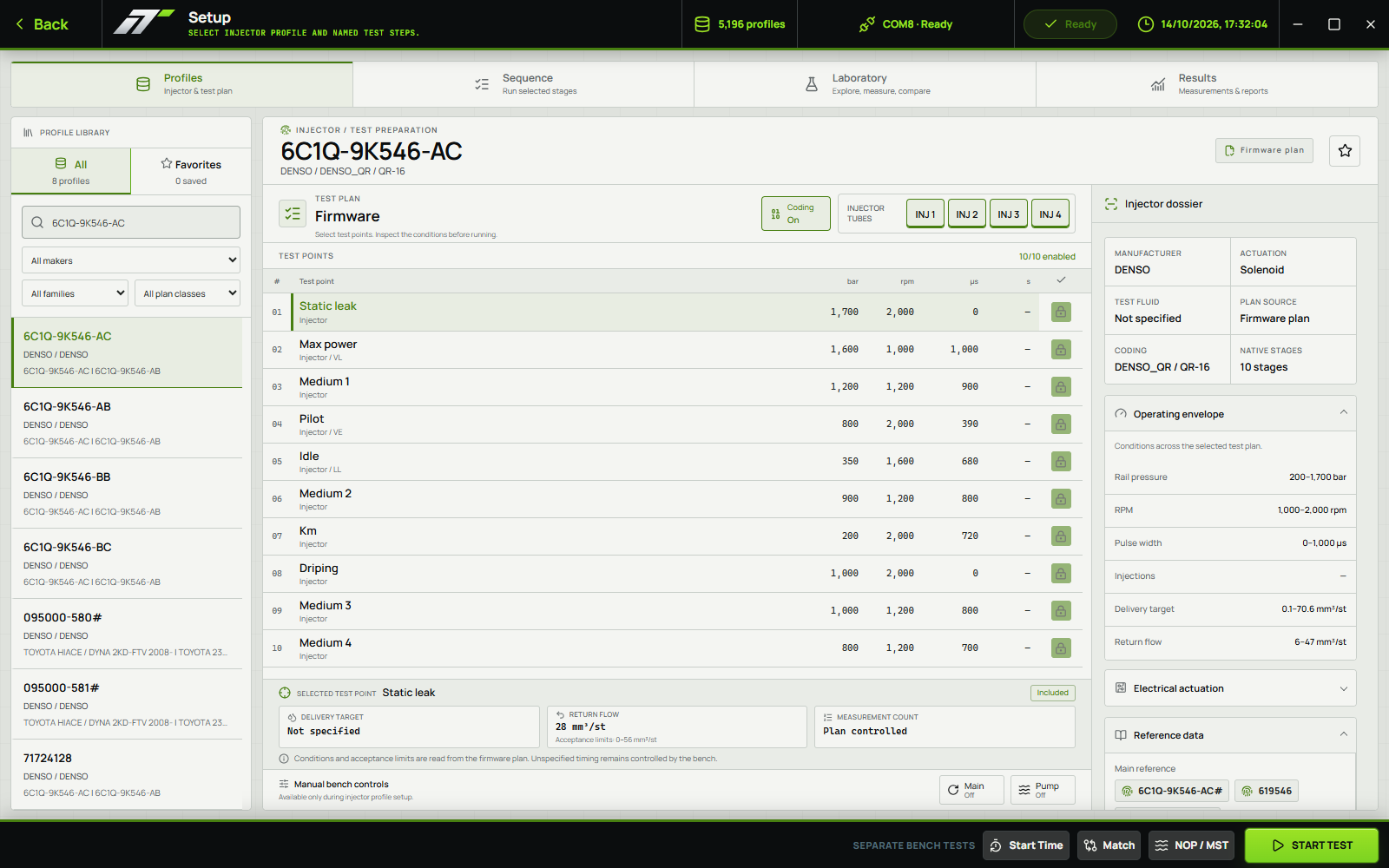
Coding availability depends on injector reference, database, software version and configuration. Generated codes require application-specific validation.
Application coverage
Confirm the exact injector number, coding requirement and necessary fixture set with the Injectune team.
Explore injector profilesTest reportProduct catalogue / 2026INJECTUNE CONTROL / The workshop record
Keep the conditions and the outcome together. A technical protocol gives the workshop a clear reference for what was tested and what was measured.
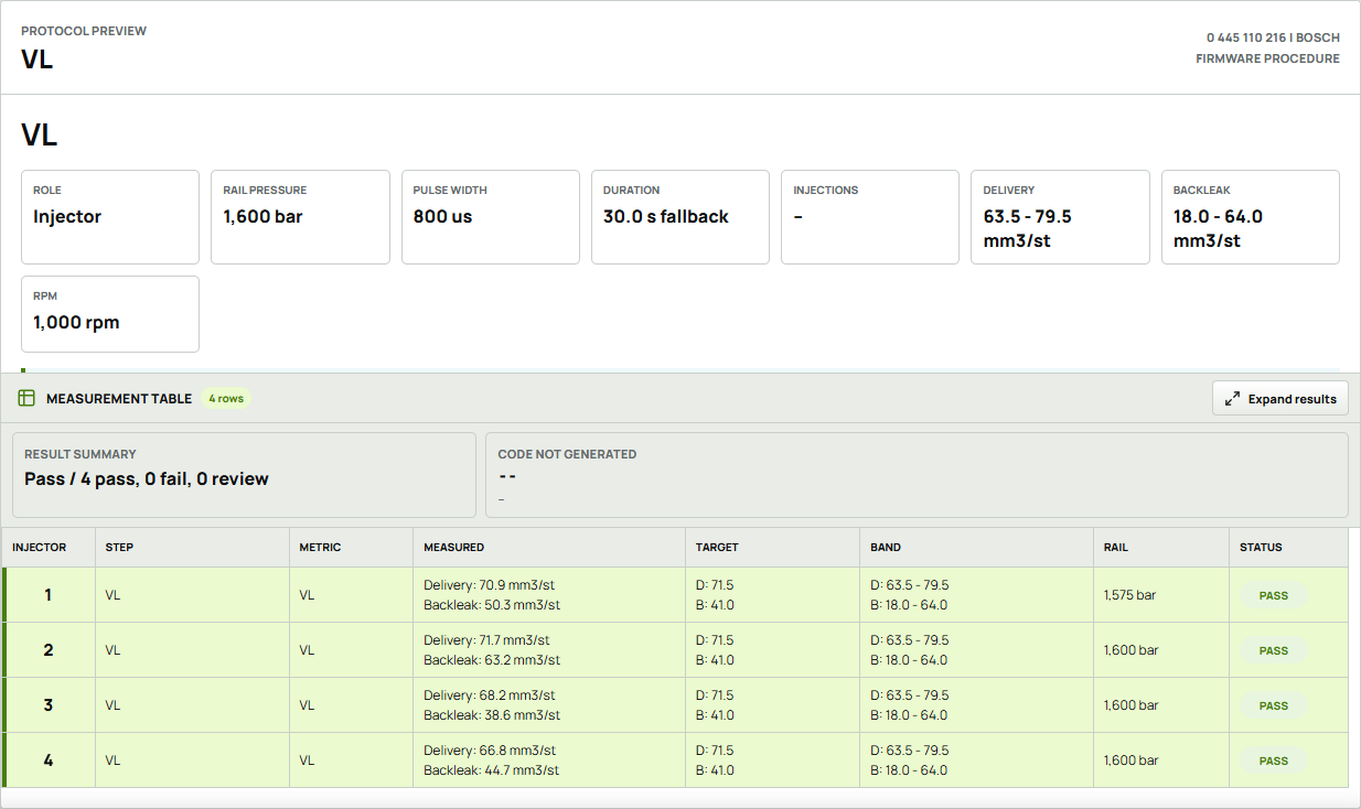
Keep the injector reference and selected test plan with the result.
Read the measurement, target band and reported status in context.
Save or print the protocol for the job record and customer handover.
English report view from recorded bench data. The session shown is a stage result, not a completed full injector certification.
Equipment & configurationProduct catalogue / 2026X1 / X4 / Supplied equipment / X1 & X4
The standard working set covers pressure and return connections, electrical connections and injector handling. Define the final quantities for your channel count and injector mix.
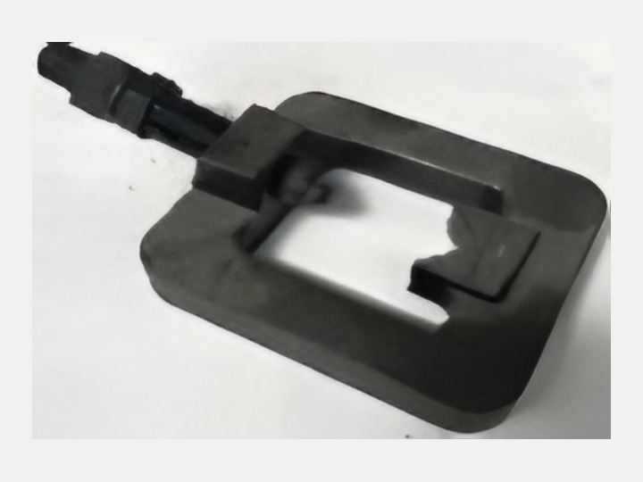
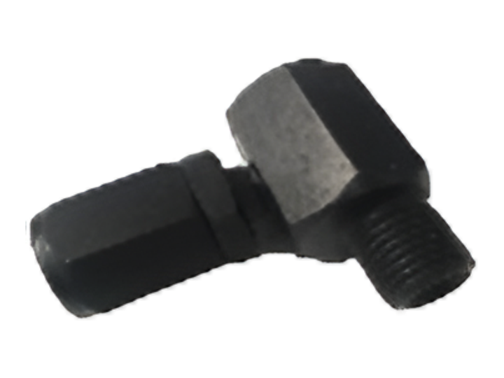
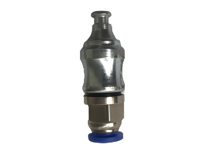
The following standard and optional lists follow the existing CR injector set record. Reference quantities are not a per-machine packing list; final contents and quantities are confirmed in the approved quotation.
Standard adapters & setup accessoriesProduct catalogue / 2026standard / X1 + X4
Injector Test Adapters & Fixtures / Setup Accessories
Provides the application-specific injector interface for the test bench. Select it by the complete injector part number and required test connection arrangement.
Example injector part number0445120007
Reference quantity 1
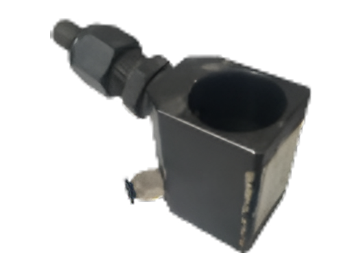
Example injector part number0445120020
Reference quantity 1
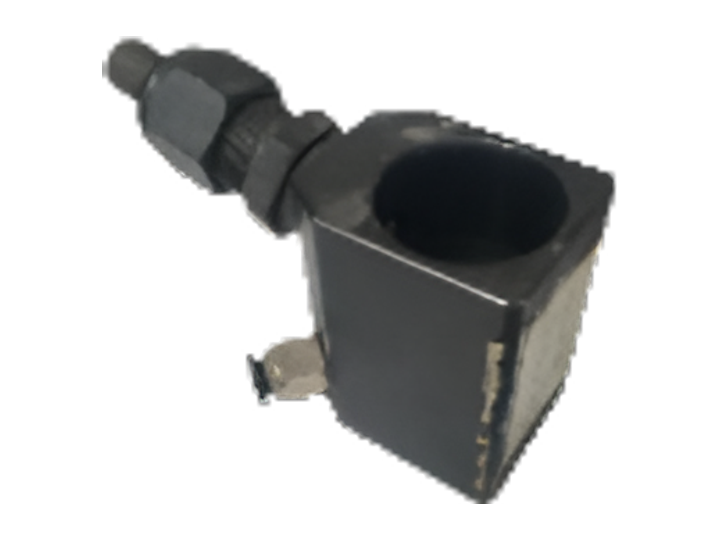
Example injector part number0445120024
Reference quantity 1
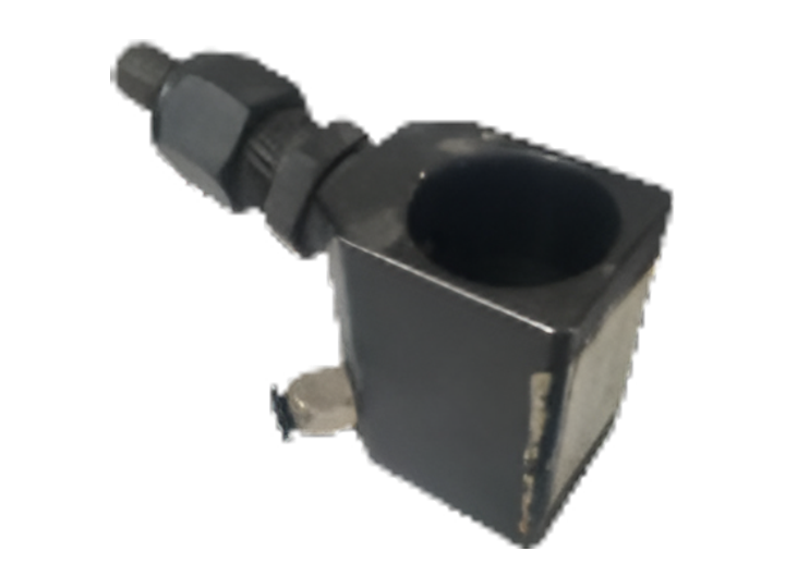
Example injector part number0445120025
Reference quantity 1
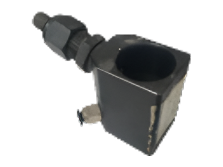
Example injector part number0445120030
Reference quantity 1
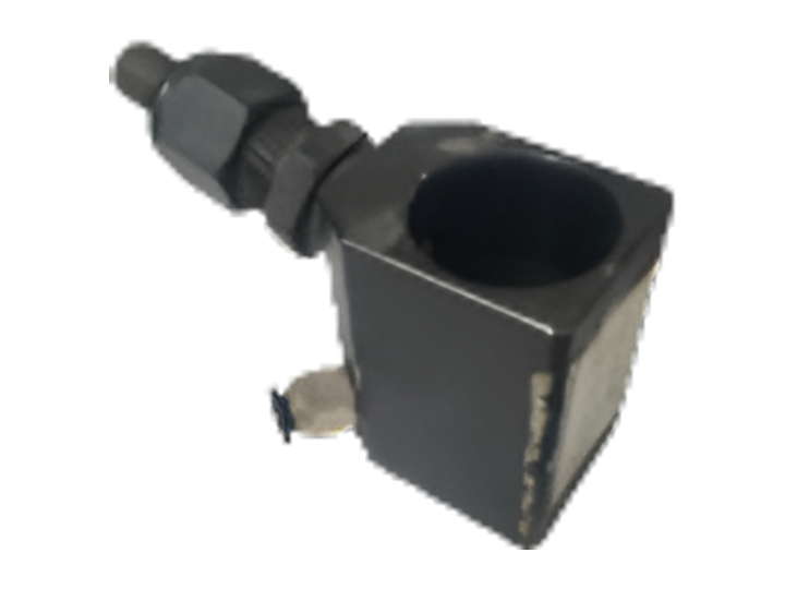
Example injector part number0445120070
Reference quantity 1
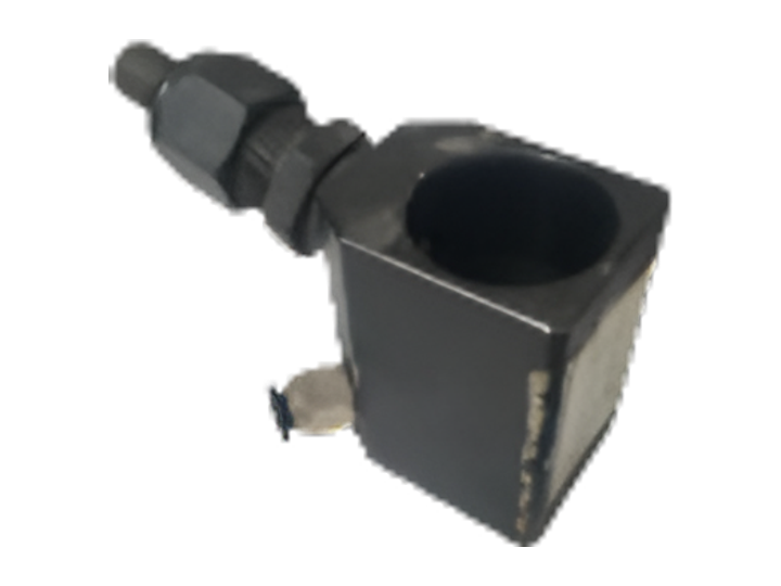
Example injector part number0445120074
Reference quantity 1
Variant informationE.B.S.A.
Reference quantity 1
Standard rail & pressure connectionsProduct catalogue / 2026standard / X1 + X4
Rail & Pressure-Line Connections
CR 432, CRL 032 and ERC 17 identify the rail T-piece, L couplings and pressure line. Thread size, sealing geometry and pressure rating all matter.
Connection specificationM14
Reference quantity 4
Connection specificationM14
Reference quantity 4
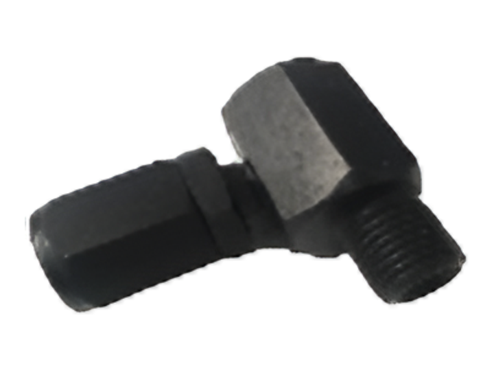
Connection specificationM12
Reference quantity 4
Connection specification14 × 14 · 410 mm
Reference quantity 4
Standard injector connection fittingsProduct catalogue / 2026standard / X1 + X4
Injector Connection Fittings
Injector connection fitting for the listed application. Match the injector connection geometry and specified fluid-circuit interface before selecting this reference.
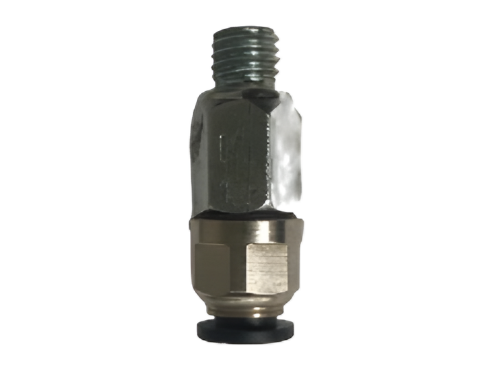
Application referenceDenso · 8 × 1
Reference quantity 4
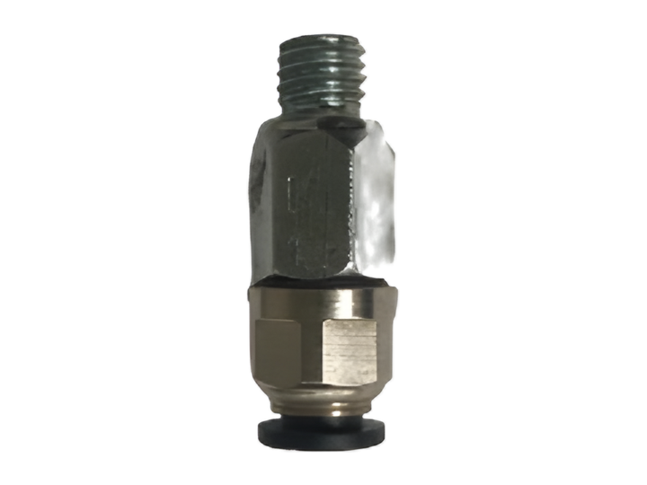
Application referenceDenso · 8 × 1.25
Reference quantity 4
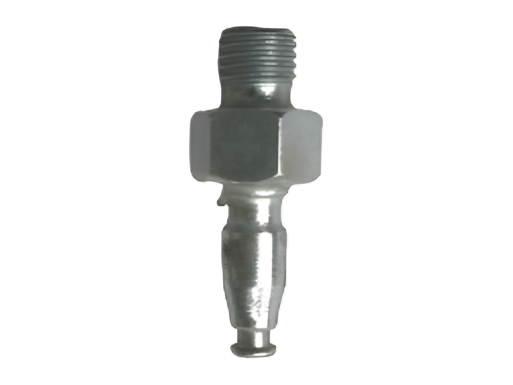
Application referenceDenso · piezo · 8 × 1
Reference quantity 4
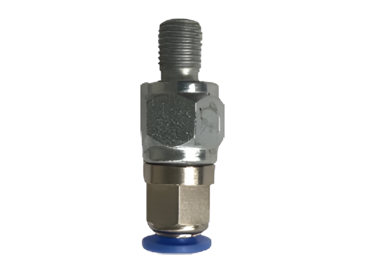
Application referenceDenso · 6 × 1
Reference quantity 4
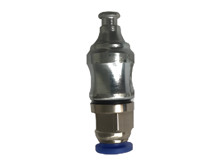
Application referenceDelphi
Reference quantity 4
Application referenceBosch
Reference quantity 4
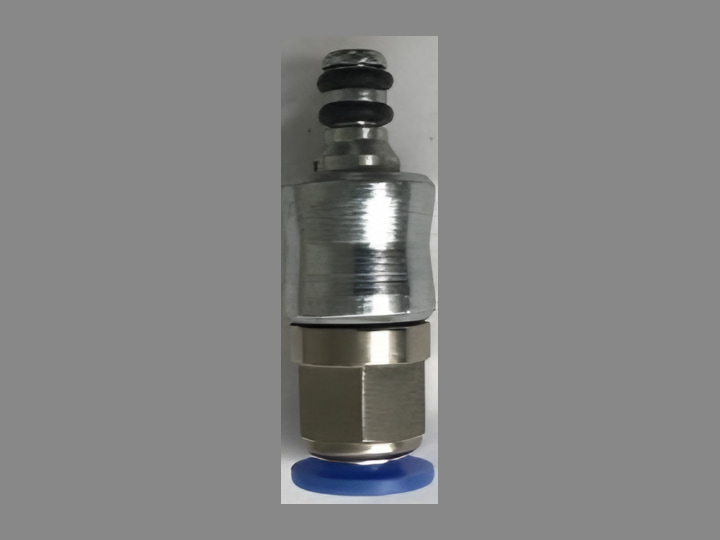
Application referenceContinental / Siemens
Reference quantity 4
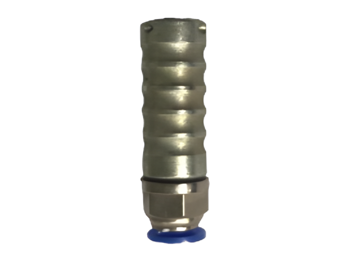
Application referenceBosch / Denso · piezo
Reference quantity 4
Standard injector cablesProduct catalogue / 2026standard / X1 + X4
Electrical Test Cables
Connects the listed injector application to the test bench drive channel. Match the injector connector geometry and documented pin assignment before selecting this cable.
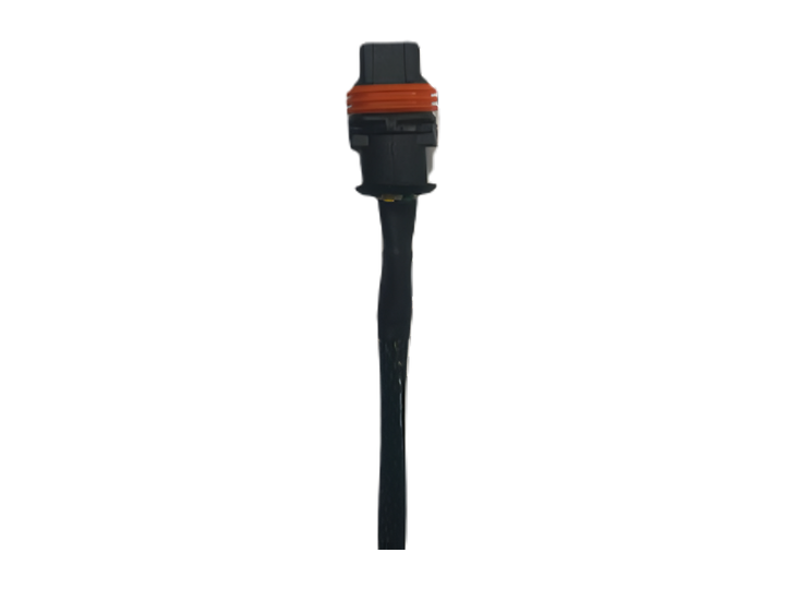
Variant informationInjector fitment to confirm
Reference quantity 4
Application referenceBosch
Reference quantity 4
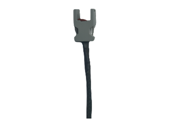
Application referenceDelphi · Type 1
Reference quantity 4
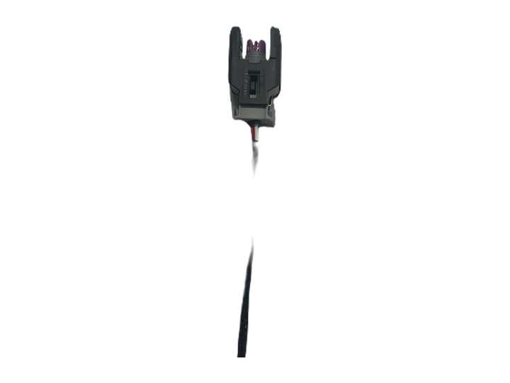
Application referenceDelphi · Type 2
Reference quantity 4
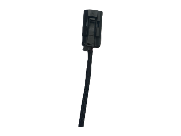
Application referenceContinental / Siemens
Reference quantity 4
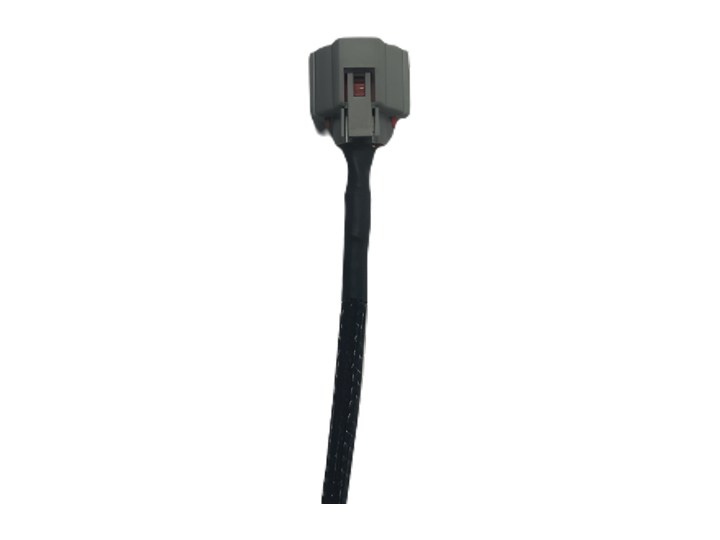
Application referenceDenso · Type 1
Reference quantity 4
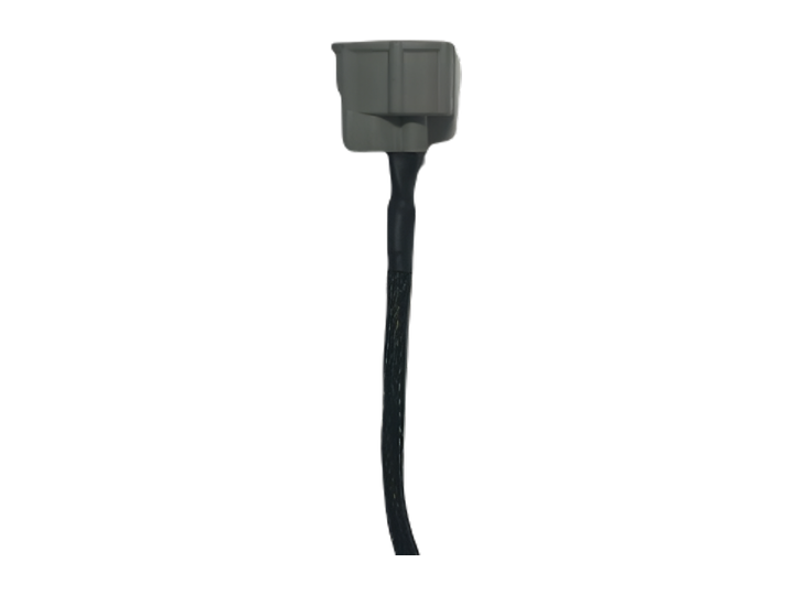
Application referenceDenso · Type 2
Reference quantity 4
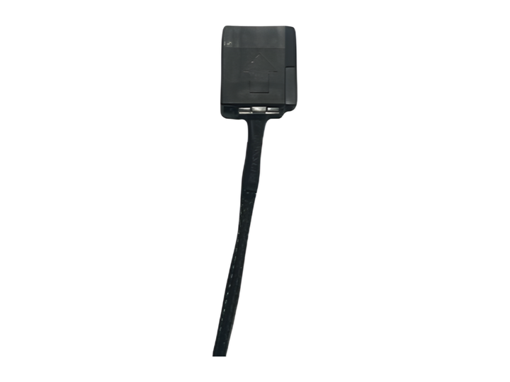
Application referenceDenso · Type 3
Reference quantity 4
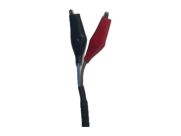
Variant informationInjector fitment to confirm
Reference quantity 4
Optional injector adapters / 1Product catalogue / 2026optional / X1 + X4 / 1 — 3
Injector Test Adapters & Fixtures
Provides the application-specific injector interface for the test bench. Select it by the complete injector part number and required test connection arrangement.
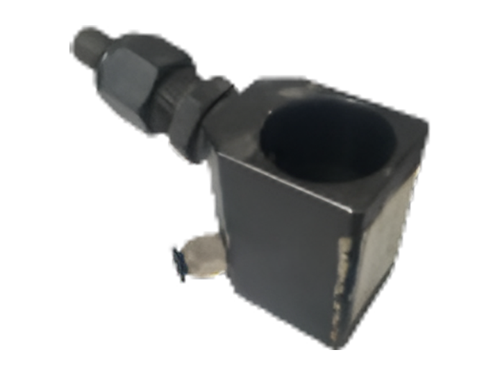
Example injector part number0445120078
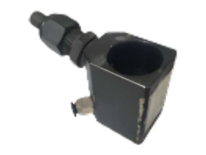
Example injector part number0445120086
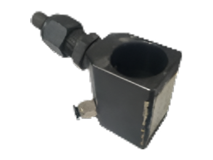
Application referenceBosch · John Deere
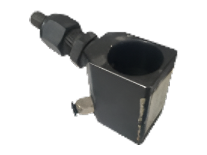
Application referenceBosch · Volvo
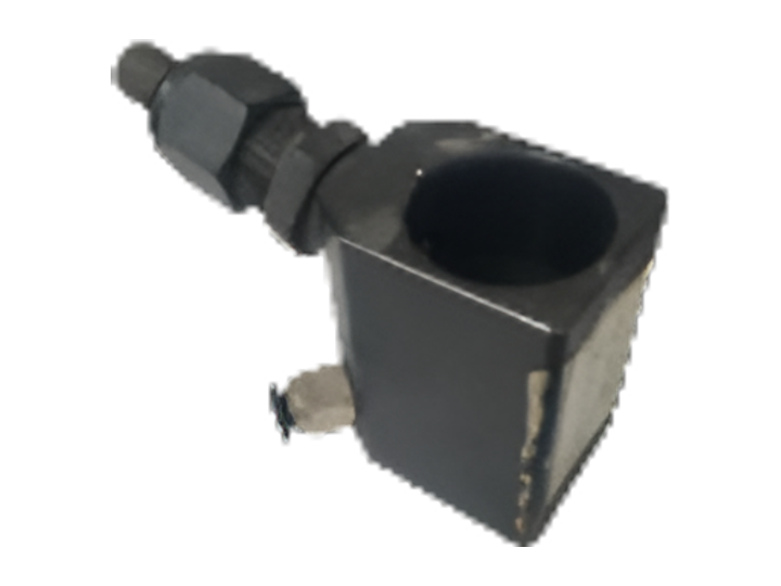
Application referenceBosch · CAT
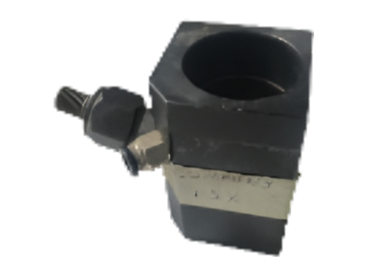
Application referenceBosch · Cummins ISX
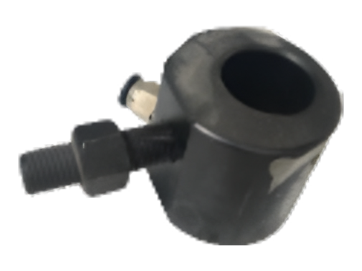
Application referenceBosch · DAF · Euro 5–6
Optional injector adapters / 2Product catalogue / 2026optional / X1 + X4 / 2 — 3
Injector Test Adapters & Fixtures
Provides the application-specific injector interface for the test bench. Select it by the complete injector part number and required test connection arrangement.
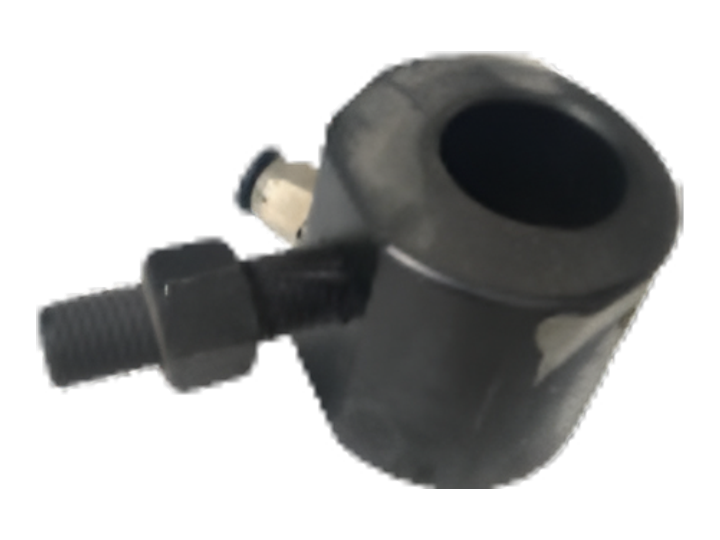
Application referenceBosch · DAF · Euro 6
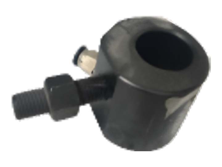
Application referenceBosch / Delphi · Mercedes-Benz · Euro 5
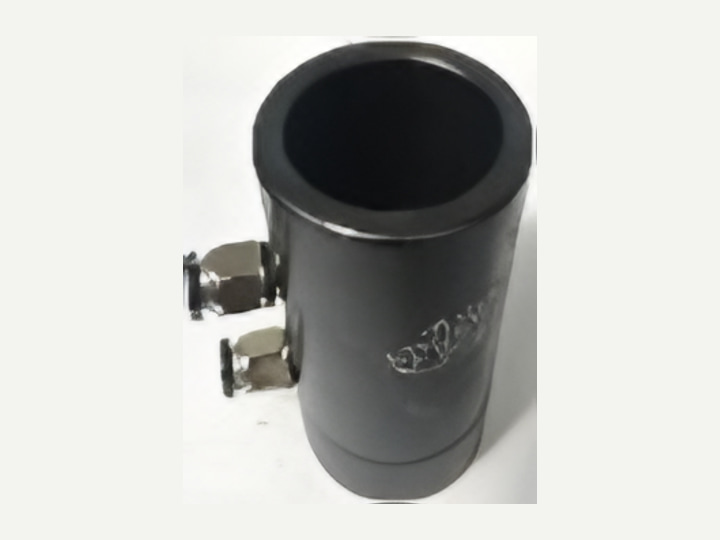
Application referenceBosch · Mercedes-Benz · Euro 6
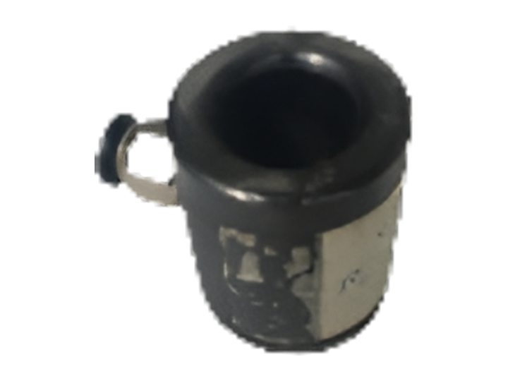
Application referenceDelphi · Volvo · Euro 6
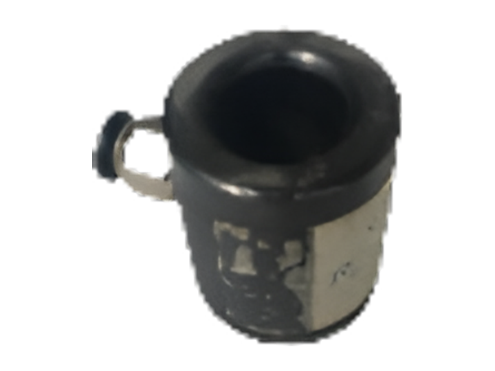
Application referenceCAT / Perkins
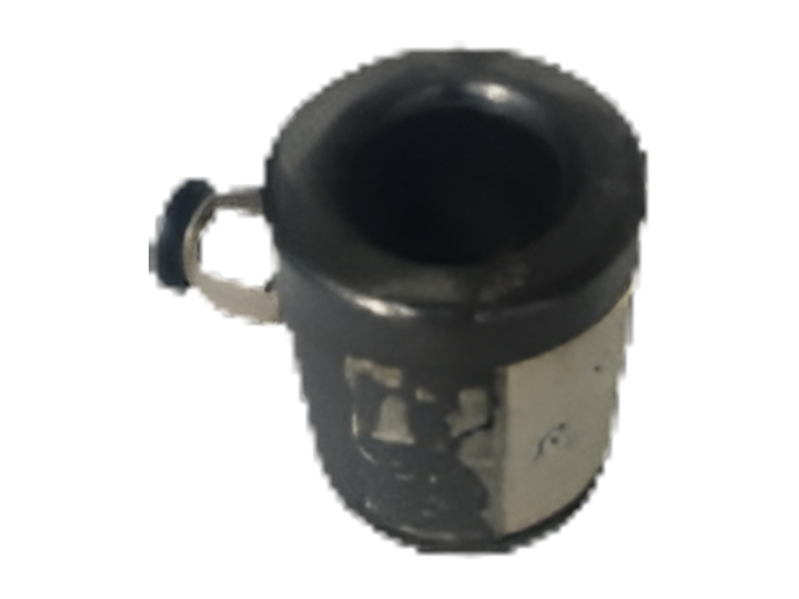
Application referenceDenso · Type 1
Optional injector adapters / 3Product catalogue / 2026optional / X1 + X4 / 3 — 3
Injector Test Adapters & Fixtures
Provides the application-specific injector interface for the test bench. Select it by the complete injector part number and required test connection arrangement.
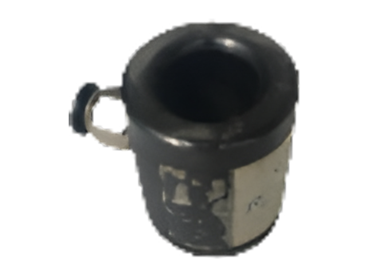
Application referenceDenso · Type 2
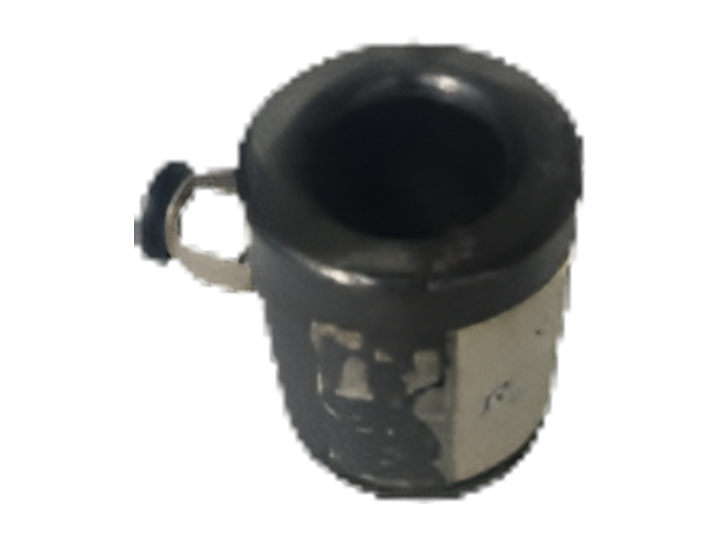
Application referenceDenso · Type 3
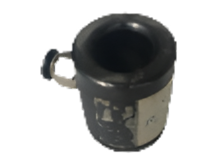
Application referenceMercedes-Benz Axor · Euro 5
Variant informationInjector fitment to confirm · Type 1
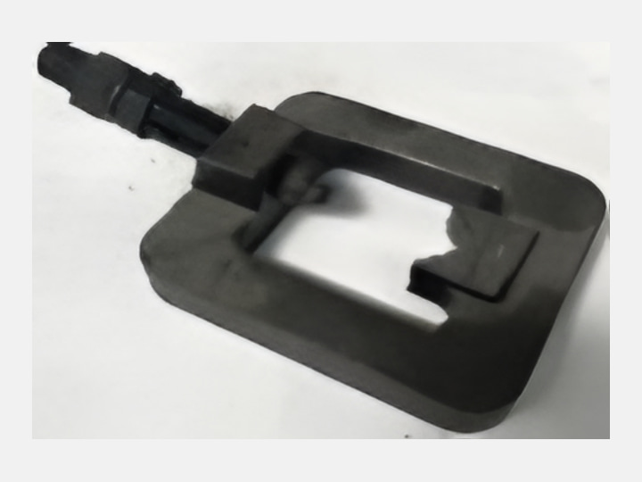
Variant informationInjector fitment to confirm · Type 2
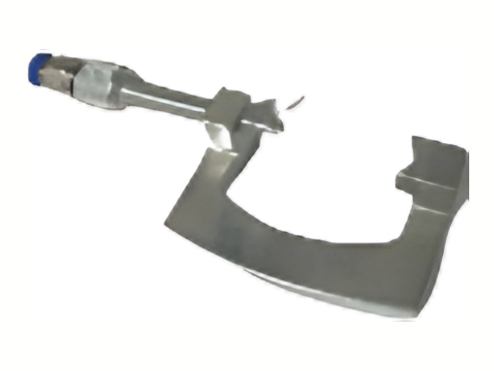
Variant informationInjector fitment to confirm · Type TA
Optional pressure connections & cablesProduct catalogue / 2026optional / X1 + X4
Rail & Pressure-Line Connections / Electrical Test Cables
Build an application around the injector part number. Mechanical fit, fluid connections and electrical drive must work together.
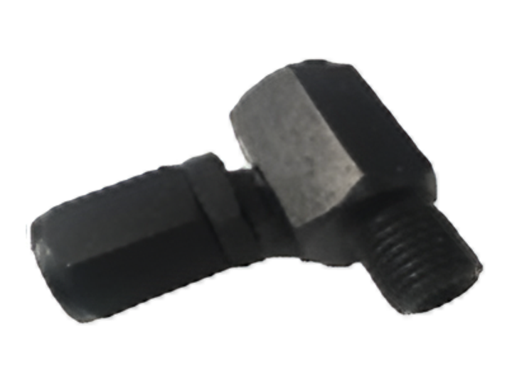
Connection specificationM16
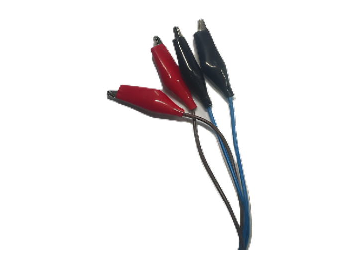
Application referenceBosch · Euro 6
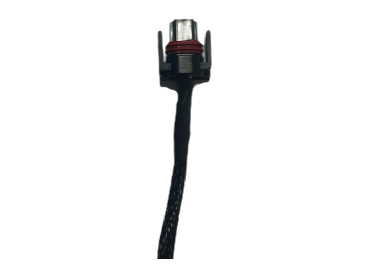
Application referenceCAT
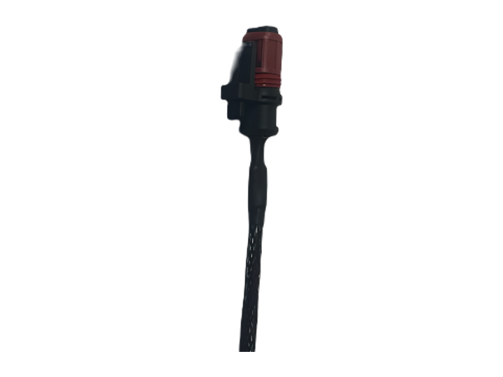
Application referenceVolvo · Euro 6
Application referenceDenso · solenoid
Application referenceBosch · solenoid
Equipment code indexProduct catalogue / 2026X1 / X4 / 29 + 25
Turn a brand or engine-family enquiry into a defined test configuration.
| Code | Application reference | Page |
|---|---|---|
| CE 306 | 0445120007 | 13 |
| CE 308 | 0445120020 | 13 |
| CE 310 | 0445120024 | 13 |
| CE 312 | 0445120025 | 13 |
| CE 314 | 0445120030 | 13 |
| CE 316 | 0445120070 | 13 |
| CE 318 | 0445120074 | 13 |
| EA 236 | E.B.S.A. | 13 |
| CR 432 | M14 | 14 |
| CG 4-D | Denso · 8 × 1 | 15 |
| CG 6-D | Denso · 8 × 1.25 | 15 |
| CG 8-D | Denso · piezo · 8 × 1 | 15 |
| CG 10-D | Denso · 6 × 1 | 15 |
| CG 12-D | Delphi | 15 |
| CG 14-B | Bosch | 15 |
| CG 16-S | Continental / Siemens | 15 |
| CG 18-P | Bosch / Denso · piezo | 15 |
| CRL 032M14 | M14 | 14 |
| CRL 032M12 | M12 | 14 |
| ERC 17 | 14 × 14 · 410 mm | 14 |
| EB 102 | Injector fitment to confirm | 16 |
| EB 104 | Bosch | 16 |
| ED 110 | Delphi · Type 1 | 16 |
| ED 112 | Delphi · Type 2 | 16 |
| ES 114 | Continental / Siemens | 16 |
| CD 116 | Denso · Type 1 | 16 |
| ED 118 | Denso · Type 2 | 16 |
| ED 120 | Denso · Type 3 | 16 |
| EU 122 | Injector fitment to confirm | 16 |
| Code | Application reference | Page |
|---|---|---|
| CE 320 | 0445120078 | 17 |
| CE 330 | 0445120086 | 17 |
| CE 334 | Bosch · John Deere | 17 |
| CE 338 | Bosch · Volvo | 17 |
| CE 342 | Bosch · CAT | 17 |
| CE 344 | Bosch · Cummins ISX | 17 |
| CE 350 | Bosch · DAF · Euro 5–6 | 17 |
| CE 354 | Bosch · DAF · Euro 6 | 18 |
| CE 358 | Bosch / Delphi · Mercedes-Benz · Euro 5 | 18 |
| CE 364 | Bosch · Mercedes-Benz · Euro 6 | 18 |
| CE 366 | Delphi · Volvo · Euro 6 | 18 |
| CE 368 | CAT / Perkins | 18 |
| CE 372 | Denso · Type 1 | 18 |
| CE 378 | Denso · Type 2 | 19 |
| CE 382 | Denso · Type 3 | 19 |
| CE 384 | Mercedes-Benz Axor · Euro 5 | 19 |
| CE 390 | Injector fitment to confirm · Type 1 | 19 |
| CE 392 | Injector fitment to confirm · Type 2 | 19 |
| CE 394 | Injector fitment to confirm · Type TA | 19 |
| CRL 032M16 | M16 | 20 |
| EB 106 | Bosch · Euro 6 | 20 |
| EC 108 | CAT | 20 |
| UV 168 | Volvo · Euro 6 | 20 |
| ED 152 | Denso · solenoid | 20 |
| EB 148 | Bosch · solenoid | 20 |
Engineering & manufacturingProduct catalogue / 2026KOMTEST / KONYA / TÜRKİYE
Injectune is engineered and manufactured by KOMTEST in Konya, Türkiye. The machine, connection set and software scope are configured around the injector applications serviced by your workshop.
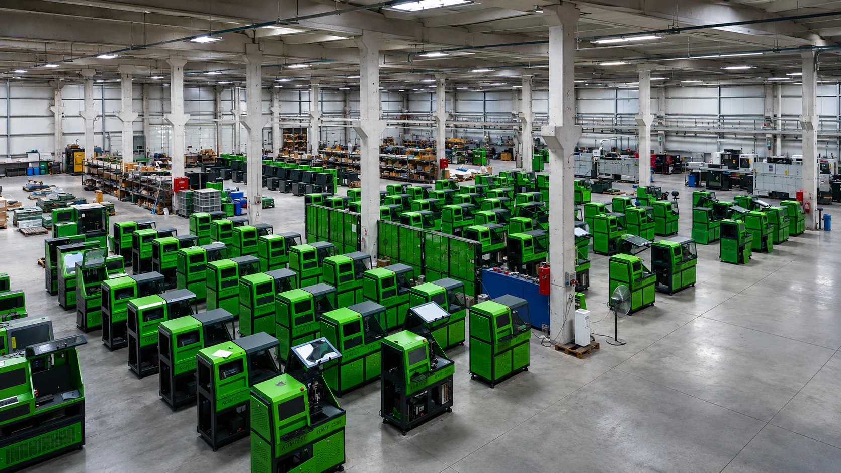

KOMTEST engineering and manufacturing.
Begin with the injectors you service and the way your workshop works. Build the machine, connection set and software scope around that application.
 Configuration & handoverProduct catalogue / 2026
X1 / X4 / CONTROL / EQUIPMENT
Agree the machine, equipment and software scope around the work your workshop actually performs.
Share injector references, manufacturers, coding requirements and your typical daily workflow.
Confirm pressure and return connections, injector adapters, solenoid and piezo cables, and application-specific fixtures.
Review the final specification, workshop layout, utilities, delivery and commissioning requirements with the team.
Confirm the installation drawing, electrical supply, test fluid, environmental conditions and service clearances in the machine-specific installation documentation.
List each included and optional reference, its variant and its quantity. Reference-set quantities in this catalogue are not a separate delivery commitment.
Use representative injector part numbers to demonstrate setup, test stages, measurements, supported coding and report output.
Include operation, approved connection procedures, routine maintenance and the agreed training and support terms in the handover.
Coding, application coverage and fixtures depend on the installed configuration. Confirm machine dimensions, utilities and final equipment with the technical team before installation.
Technical salesProduct catalogue / 2026INJECTUNE X1 / X4
Clarity under pressure.
Technical sales
info@injectune.com+90 538 718 43 16injectune.com Let’s build your configurationEngineered and manufactured by KOMTEST.
Konya, Türkiye.
English edition / 2026
Technical data subject to final configuration.